Dodge Durango Forum banner

Off road light wired to high beam

13K views 32 replies 6 participants last post by  Oslo D  
#1 ·
Hello everyone, I have a 2000 dodge Dakota slt. I recently purchased some off road lights for it, I have them mounted but I'm trying to figure out how to wire them into my high beams with a relay? I don't want a extra switch I just want them on the same time my high beam lights are on, does anyone know how to do this? Any help would be greatly appreciated

Sent from my SAMSUNG-SM-G870A using Tapatalk
 
#2 ·
Don't know where you live, but that would be terribly inconsiderate and illegal. You can't run off road lights while driving on the streets/highways in most states. Wiring could be problem since headlights are controlled by a switched ground. Better to wire on separate switch.
 
#4 ·
You could simply tap into your factory wiring... But depending o what type of lights they are (halogen, HiD, LED) I'd be worried about overloading the factory harness
 
#6 ·
If the lights ground through the housing you could have problems. The headlights have power to them all the time, the switching capability is done with ground circuit.
 
#7 · (Edited)
I agree with the above cautions. However, assuming this vehicle is exclusively used off road, consider the following...

Connect the relay control pins as follows:
-One pin to Highbeam switched ground signal wire behind headlight.
-other pin to positive signal wire behind headlight. Use fuse on this wire.

The above will only close the relay when the high beams are turned on. Since you may not be familiar with circuits, I recommend using an ohm meter at this point to verify the circuit between N.O. and Common are open when Highbeam switch is off. Similarly, these two pins should "short" (close) when the highbeams switch is switched on with headlights on.

Now, since you state the new lights are grounded via the bumper - that leaves a positive wire only that needs to be dealt with since the lights are already mounted. Connect the following to complete your setup:

- connect the single wire from each light to the "common" pin on the relay (only these two wires from lights).
- connect the Normally Open (N.O.) pin on the relay to a wire connected to the positive battery post, use fuse on this wire.

Note, the Normally Closed (N.C.) pin would be the opposite of what you want. So no wire to this relay pin for this setup.

If you need more help, please post a photo if YOUR relay pins and I'll assist further.

Using the relay will help prevent your headlight circuit from being over loaded since the current driving the new lights will pass through the relay pins/contact, not through the Highbeam circuit. It also gets around the switched positive wire requirement of the new lights.

Regardless, I recommend installing two fuses on this setup. One between battery positive oost, close to battery. Second one between positive signal wire behind headlight and relay, closer to factory headlight wire harness end. Use fuses recommended or supplied in new light kit. The relay should also be one from the kit if not, many will work - just be sure it is rated for the current draw of new lights. The switching side of relay (side that creates magnetic field to pull relay) should no add too much to the Highbeam circuit.
 
#8 · (Edited)
Relay pins 85 and 86 are the electromagnetic control pins that when energized, will close/short pins 30 and 87.

So you can connect the switched wire from the headlight highbeam switch to say pin 85.
Connect pin 86 to the positive wire behind the headlight Highbeam buls harness.

It really does not matter if you swap/reverse pins 85 and 86. Either way, the relay will close when Highbeam switch is turned on.

You can connect pin 30 of the relay to fused wire to battery's positive post.
Connect pin 87 of relay to new lights. If there are two pins labeled 87 (do NOT use 87A for your setup), then each light can use it's own 87 pin. Other side connect both lights to the single pin 87.

Again, it really does not matter if the battery is connected to pin 87 or pin 30 - unless there are two 87 pins, then take advantage and use both pins for each light and battery to pin 30.

The above information assumes the headlight switch is indeed negative (-) switching. If it is positive switched for factory light switch, then the other wire behind the switch would be negative, not positive since the switched lead from the headlight Highbeam switch would be positive. This is quite easy to fixture out with a ohm/volt meter, so recommended.

Don't focus too much on why the numbers of popular relays are typically 30, 85, 86, 87(n.o.), & 87A(n.c.), if present.

Just remember pins 85 & 86 are used to close the relay so relay control pins. Pin 30 is typically the common/12VDC power source and pin 87 receives that 12VDC power when pins 85 & 86 are included in an energized/switched circuit.
 
#9 ·
What I did in the past was wire a really to control the positive feed to the lights, then have one of the solenoid pins always wired to 12v. Then I had a switch in the cab which was connected to the other side of the solenoid. This switched toggled between the switched ground of the headlights high beam, off, and a chassis ground. This gave me lights on with high beams, always off, or always on depending on the switch position.
 
#11 ·
Here's an edited depiction of what your wiring could look like. Note, you can connect to either the Low beam or High beam for the "master" lights On or Off.


Then use the optional auxiliary switch located at the dash to control the new lights from being enabled for only "off road" use. If you do not install the auxiliary switch in-line to the relay, using the high beam output signal from the headlight switch will work as you requested.

As others suggested doing so is a poor choice for on-road vehicle use as another driver will inadvertently get blinded at night - if not by you, by an unsuspecting someone else driving your vehicle.

More data can be found here:

How To Wire Fog And Driving Lights Harness Wiring Diagram
 
#33 · (Edited)
... edited depiction of what your wiring could look like. Note, you can connect to either the Low beam or High beam for the "master" lights On or Off.

View attachment 36849
Posts #7 and #8 are logical for a negatively switched system on 98-99-00 models. The diagram in #11 is a traditional diagram for positively switched circuits. To agree with Posts #7 and #8 I think the 86 'ground' should tap into the headlight 'ground', connected with a wire. Alternatively, run the 86 'ground' positions into a switch inside the cab and back to the headlight 'ground' .
 
#13 · (Edited)
Right, you should be able to "tap" into the harnes of one head light. This is going to be the source to control/activate the relay to switch n power from battery positive terminal to flow to the new lights you installed.

The photo isn't too clear to what wire is doing what - seems like a lot of splices taking place.

If you are unsure about wiring/schematic, ask a buddy to help work through the setup. If Yu have a ohm/volt meter, I recommend using it before moving forward. What yo font want is to skip the use of fuses and/or rei burning up circuits. That gets expensive to diagnose and correct.

You mentioned you broke one bulb. The the should still work. Do the new lights turn as expected?
 
#24 ·
When measuring power at the head lamp assembly, you should disconnect the harness from the lights. This will prevent you from seeing power or ground through the lamp's element.

At this point, I recommend disconnecting what you did before the relay install attempt. Reconnect any wires that were cut, verify currently installed bulbs and factory fuse locations are not blown. Then test the factory light switch. I'm not trying to waste your time - this is easier and therefore less cumbersome without the additional complexities of the additional relay circuits recently added.

Once the above is verified, connect the new auxiliary lights to the relay to pin(s) 87 on the relay. Connect a fused wire to the positive terminal of the battery and pin 30 on the relay. After this is done, you can test the relay and aux lights by temporarily connecting pin 30 to either say pin 85 of the relay. Now, connect a temporary wire from pin 86 to a known good chassis ground point - even if it's the battery's negative post. Doing this, should "activate" the relay and send power to the aux lights.

Assuming your headlights are now working, you will be close to get the rig setup the way you want. But, to ensure we are good, we need to follow the above steps without shortcuts or skipping steps.

Please keep us posted.

I'll PM you with my phone number if you want to talk it through, feel free to txt or call me this weekend.
 
#25 ·
Wire taps can cut the wire you are using as the source and not feed the lamp that they are supposed to. Check the current flow after the tap to make sure lamp is being fed.
 
#26 ·
Based on the image Matt provided, it looks like you should eventually be tapping into Pin-C (L3 14RD/OR) which is fed from the High Beam output at the Dimmer/Light switch.

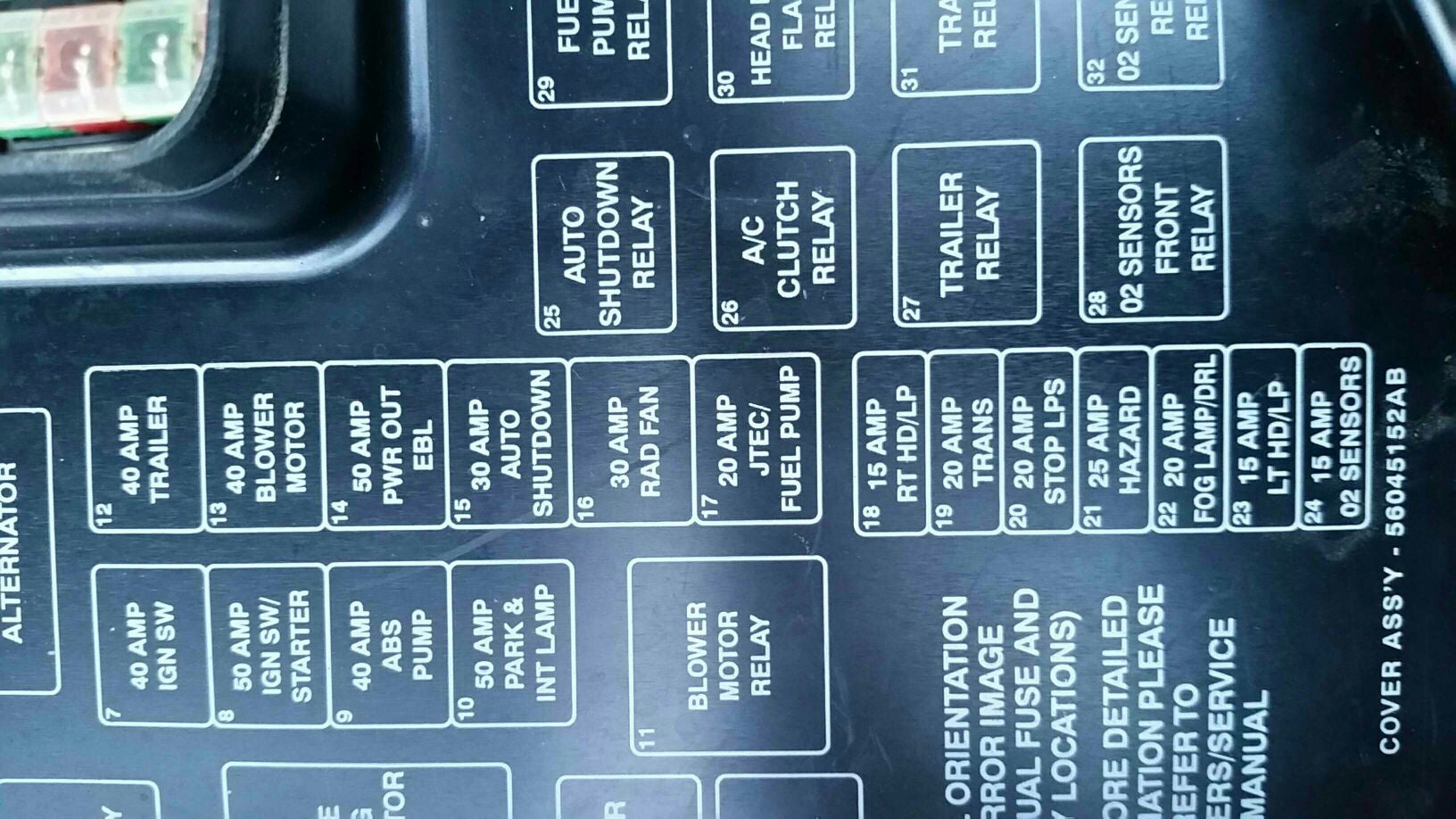
You will need to first verify this wire receives 12VDC Positive when the High Beam switch is ON. To do so, disconnect the bulb at socket, put the Red test probe in the socket and the Black probe on chassis ground. Switch Off, no VDC. Switch on should see 12VDC. If not voltage is seen, check the factory fuse at #23 in fuse panel.

As Mike suggested, it's best not to use crimp-style wire taps. I would carefully remove a short section of insulation, split he wires apart and thread the new wire through it like a needle and thread. Then, twist the new threaded wire around the original wire you are tapping into and solder then together followed by a good wrap of electrical tape. This is once you verified all is working as a final phase to the installation.